
How to or how should I winterize my car?
 Would you like to be trapped in twenty degree weather with a broken down vehicle? Would you like to have to wait for a tow truck to come pull you to the garage? Would you want to fix your vehicle while it is snowing outside?
These are all things that preventative maintenance and several checks can help reduce from occurring.
Preparing your vehicle outside
There are several things that an average person can do to help maintain their cars exterior for the winter. A good idea of something to do before the first snow even occurs is to wash and wax your exterior of your car. This helps clean the exterior and the wax helps create a barrier between the harmful road salt and other deicers which can damage your vehicles paint. This barrier helps prevent rust from occurring. Of course you are still going to need to wash your vehicle during the winter, but this is where car washes come in handy, especially the ones with the under wash. This under wash helps wash the buildup of deicers, salt, and road dirt from the slushy winter roads out from underneath your vehicle, helping to prevent rusting of critical parts.
Preparing your vehicles tires
By taking care of your vehicles tires before the winter starts, helps prevent the need to fix a flat in the blowing snow. A good idea also is to check your vehicles tire wear. For the average person who would like to check their tire wear it is a fairly simple procedure; however, if you are not comfortable with checking your tire wear by yourself you can take your vehicle to a mechanic and have them check your tire wear and pressure all at the same time.
The procedure for checking tire wear
- Take a penny; your average Lincoln penny and place in your tires center tread upside down so Lincoln’s head is facing down.
- Next if your tread touches or passes Lincoln’s head then your tread should be good if your tire is wore even which I will discuss later. If however the tread doesn’t touch Lincoln’s head then you likely need new tires and should consult a mechanic or a tire shop.
- How I stated before if your tires are wore even, then you should be set if you do the above test. If not however this is a quick way to check. All you need to do if you’re comfortable with checking is look at your tires. See if they are worn more in any spots, or if they are uneven looking. The best bet is to move the car a little to check the whole tire. You should also check for any cracks, nails, or other objects that can show either wear or a possible spot for failure.
Another simple task that you should do before winter with your tires is check to make sure your tires are properly inflated with air.
- To do this you first need to locate where your specific tire pressure is located. This can be on the side of the door when opened in a vehicle, on the gas lid, or if you can’t find it then you can look inside your owner’s manual. Generally I just look at the “max PSI”<–(lbs. per square inch) labeled on the outside wall of your tires. Might have to get your cheaters on lick your fingers and rub the tire wall to be able to read. It could say something like (MAX PSI 40lbs.)
- Next if you feel confident in your skills all you will need is a tire pressure gauge from any auto parts store while you are there buying oil. They are very inexpensive such as a few of the ones listed here and you can just keep one in your glove box for each vehicle. If you don’t have an air compressor several of gas stations have them complimentary. Always keep your tires inflated to the MAX PSI for best vehicle mileage and handling. It will also insure even tread wear over the tire’s lifetime.
- To accomplish your air pressure test your vehicles tires must be cold which means that you have not driven your car recently. All you do to check your tire pressure is use your numbers you found from your research on your car and take the air caps off of your tires. Then you take your air pressure gauge and make sure to push it all the way on the valve stem for a second or two. You should hear a sound of air rushing.
- Then you record the reading on your air pressure gauge.
- If your tires are low then you fill air as needed by putting the air nozzle from the compressor on the valve stem for a couple seconds at a time. Make sure to check the air pressure every time you stop for filling.
- If your tires are over inflated then you will need to release some air by using your finger nail or something small to hold the valve open on the tire. Do this for a couple seconds and then re check tire pressure until your pressure is the same as what it should be.
Note: Don’t check tires by simply looking at them and seeing if they are low or full this way, it can be very misleading. Always consult the specific number on the side of your door or in your owner’s manual. As cold weather sets in……..air condenses or becomes thinner thus reducing the lbs. per square inch inside your tires so I always wait until temps get below freezing and check the pressure again. If you live in North Dakota like me wear gloves and wait until the wind calms down a bit before doing this……….don’t wait until it’s -20 below and 40mph winds!
Now after accomplishing these simple procedures or taking your vehicle to a trained mechanic to have them done you may feel satisfied that you are protected in the tire area. This is wrong! A lot of people only check their tires on their car; however, you should also check your spare tire! Do the same as you did before with the other tires, look up the pressure (it should be in the same place as mentioned above if not you can check the spare tire compartment and it should say), and then add air or remove air as demonstrated above. Along with checking your spare you may also want to check to make sure that your vehicle has a jack and it is in the vehicle, and you may also want to check to make sure that the vehicle has a lug nut wrench that fits, and that it is in the car. After doing all of these things you should be pretty much covered on the tire situation.
Checking your vehicle’s systems
Now that you have accomplished the basics such as your tires and exterior, we can move onto some other things that you should check before winter. Some of these are more advanced and may need to be taken to a mechanic. We will discuss how to check your vehicles battery, your pH level in your coolant, your washer fluid, and your oil.
We will start out with the battery. This is often overlooked until those cold mornings when you go to start your vehicle and nothing…no click or anything or your car barely turns over. This can a lot of times be prevented by a couple fairly simple procedures. Again if you question your ability at all on these seek a mechanic, especially when dealing with batteries. Make sure to have baking soda handy too, since this neutralizes battery acid. Always wash hands after dealing with batteries. Also note that anytime you are dealing with batteries wear safety glasses, the acid from them can burn your eyes. If a battery explodes the safety glasses will prevent the acids from entering your eyes and possibly blinding you. I know that I said a battery can explode and yes it can if hooked up wrong the hydrogen released by a battery can cause it to explode from a spark from incorrectly installed battery wires, or other open flames.
The procedure
- First make sure that your car is shut off.
- I will start with the basics, and then go into more advanced checks. Second you can check your battery for any acid or corrosion on it. Take a look at the battery terminals, the spot where the wires connect. Make sure the terminals are tight and not corroded. A great tool for this procedure and also makes a perfect gift for any mechanic is the EzRed BMK1914 Battery Terminal Maintenance Kit.
- If the terminals are not tight and you feel like you can tighten them then go for it just make sure to use the proper size wrench. Also make sure to not touch both terminals with the wrench or any other conductive material this can cause a short.
- If your terminals look corroded and you would like to clean them then this is the process.
- Start by removing the negative terminal on the battery this is usually the black wire, but to be sure check the battery and look for the “-” sign. Remove this wire using the proper socket or wrench included in the EzRed BMK1914 Battery Terminal Kit.
- Next remove the positive terminal on the battery usually the red wire, but just check to be sure and look for the + sign on the battery. Remove this wire using the proper socket or wrench.
- Next obtain a battery post cleaner included in the BMK1914 To use this you put the terminal in the open end and turn it, and then twist it and get the brush out and put it in the wire end and clean the clamps.
- Now you are done with this and you connect the positive wire first, then the negative. Make sure you connect the wires to the proper terminals.
- Now that your posts are clean and reinstalled you can go ahead and check your battery. To do this you will need to obtain a multimeter such as ATD-5519 Auto-Ranging Digital Multimeter this one from tooldesk.com.
- Next make sure the car is not running and take your meter out and select the DC Voltage since it is your battery. If you doubt your ability on this you can take your vehicle to a shop and have them do the test.
- You hook the red wire on the meter to the positive post on the battery and the black wire on the meter to the negative post on the battery. You should receive a reading between 12.5-12.8 DC Volts. If you do not then check again and if not again your battery may need to be replaced.
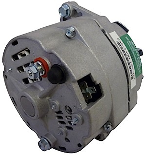
- The next test that you can do with this same meter is to check your alternator output. To do this you should first know what your alternator is. It is driven by your accessory belt and helps charge the battery and provides the voltage for the systems on the car to run. If your alternator isn’t charging your battery this could lead to a dead battery.
- To test your alternator output you will start your engine. Again select DC Volts on your meter.
- Take the leads and connect them the same way as above. This time you should receive a reading between 13.6-14.3 Volts. If you don’t then your alternator may not be charging your battery and should be further tested.
These tests can all be performed by the average backyard mechanic and even the average person, but if you don’t feel equipped enough then take your vehicle to a trained mechanic. These simple tests can help prevent you from being stranded with a dead battery.
Next we will talk about checking the pH of your coolant. This helps prevent the freezing of your coolant inside your radiator. Note coolant is poisonous and should be kept away from children, and pets. Never pour coolant down the drain without consulting your local lays regarding this.
The procedure
- First make sure that your car is not running and has been sitting for at least an hour to cool completely. Warning removal of a hot radiator cap will cause boiling coolant to shoot everywhere.
- Next locate your radiator it is under the hood and in the front of your engine. It should be rectangular and have little cooling fins and a fan near it. Once you have located your radiator locate your overflow tank which should be clear and near the radiator. Once you have located this check the cold line on the mark since your vehicle is cold and make sure the lines meet up. If they don’t add a half half mix of coolant and water until they do.
- Next remove the cap, once the cap has been removed use a pH gauge such as Thexton 100 Propylene Glycol Anti-Freeze and Coolant Tester from tooldesk.com to check the pH. To accomplish this stick the hose in the radiator and squeeze the rubber ball at the end.
- This will fill the clear sight glass with coolant. You will have to look at the number of balls floating in the tester and consult the chart with your tester. This will tell you how cold your antifreeze is rated for. If you wish to be a bit more scientific use a Coolant and Battery Refractometer which will come with instructions.
- If it is rated for not cold enough add more antifreeze. Not a 50:50 water/antifreeze mix, but pure antifreeze. It’s like not enough chocolate syrup in your malt………don’t mix the syrup with milk jut straight syrup. Get it? <—that’s the only analogy I could come up with…….I just made homemade ice cream yesterday.
Now that your coolant system is ready we can move onto your washer fluid. This seems simple enough, but it is often overlooked. If your washer fluid is not freeze resistant as soon as you reach below freezing it will freeze solid in your reservoir tank, expand and crack tank and fittings thus resulting in a dirty windshield and repairs.
The Procedure
- The basic procedure for this is before winter make sure to use up all of your washer fluid and replace with freeze resistant washer fluid. I recommend using the fluid that is supposed to melt the ice. If however you are stuck with the fluid in your tank there are two things you can do.
- One you can run your wipers with the fluid button held until you run out.
- Or you can use a siphon like the ATD 82350 and siphon the fluid out of the tank.
- The siphon is simple you put the hose in your washer fluid reservoir, and the other end in a container to store the fluid and pump the ball until fluid comes out, and then it will just run out.
The last step in preparing your vehicle for winter is changing your oil. This is often not needed in the present days due to the multi weight oils, but if your oil is not multi weight oil, you will have to change to thinner winter weight oil.
The procedure
- First if your vehicles oil needs to be changed to winter weight wait until it is starting to get cold out. You don’t want to be running thinner oil in your vehicle when it is still warm out.
- Start out by either jacking the front of your vehicle up or driving it onto car ramps. If jacking make sure to use a proper location for the jack, and also to lower the vehicle onto properly placed jack stands so the vehicle doesn’t fall on top of you. Also block the back wheels so that the vehicle will not roll off the stands or the car ramps.
- Once your vehicle is jacked up in the air. At this point I would imagine that you have changed oil before or at least have the help of someone who has. If not I would suggest watching someone change the oil or take your vehicle to a shop and have them do this for you. Now we will get a list of the tools you will need.
- A creeper such as a Mechanic’s Creeper from tooldesk.com. One that lays flat to the ground to maneuver under the vehicle
- A socket set metric or standard depending on your vehicle
- An oil filter wrench such as Oil Filter Pliers/ Wrench. There are several types and sizes depending upon the style and or diameter of your filter
- The proper o ring for your drain plug
- The proper weight oil for your vehicle
- The proper oil filter (This and the oil should be able to be looked up on the internet or where you buy your filter and or oil. Or you can likely find this in the manual).
- A drain pan such as one of these or a lift drain if you have a hoist.
- A funnel or a good Oil Dispenser like the LISLE 19732 (no funnel needed).
- Rags
- Now that your vehicle is in the air, get on your creeper, grab your sockets and drain pan and slide under the vehicle. Once under the vehicle locate your oil pan and look for a bolt head sticking out. This is your drain plug. Match the right socket to the bolt and put this socket on your ratchet and remove the bolt. Be careful when you get to the end so that you do it by hand and slow so you can position your oil drain pan to catch the oil. It is a good idea to have a few rags handy.
- Now let that drain for a couple minutes until it is completely empty. Once it is drained wipe the drain plug clean. Put a new o ring on the plug and tighten it back in. Don’t over tighten the bolt it just needs to be fairly tight.
- Now move your oil pan and your creeper and locate your oil filter. This is kind of tricky you need to remember which way to put your oil filter wrench on. It needs to pull the band tighter and to the left it may take a couple minutes but just look at it. Once you figured that out then remove your oil filter. Make sure to have the pan under the filter.
- Now set aside your old oil filter and drain pan. Grab your new oil filter, take some of your new oil on your finger and rub around the o ring on the filter to help it seal better. I always add oil inside the oil filter first before screwing it back on to get quicker pressure on first startup. Now you can use your hand to tighten the filter. Tighten until it is hand tight, then give it a quarter turn more with the oil filter wrench.
- Now take off your oil cap which is usually located on the valve covers. Remove this and place a clean funnel inside of the opening. Open your oil containers and pour however many quarts of oil your manual says to use in. Once you are done filling it replace the cover.
- Now lower your car back down to the ground. Start the vehicle and let it run for a couple minutes. Then inspect underneath the car to check for oil leaks. Next, turn the vehicle off and let sit for 10-15 minutes and then remove your oil dipstick. Wipe it with a clean towel, put it back in, remove, check the level, then wipe again, and put back in place. Make sure it is in the ok area on the dipstick or the “Full” mark.
- Now take your used oil and oil filter to a local place that recycles the oil.
Now that you have changed your oil you should be ready for the winter season. These are just the basics that the everyday go getter or backyard mechanic can accomplish. These few simple steps of preventative maintenance can be the difference between being stranded outside in the freezing cold and just enjoying the drive.
Written by Cody Mammenga NDSCS Student
 What should I put in my vehicle in case I am stranded in a winter storm?
 A common problem among vehicles is heating concerns. In this article we will discuss what occurs when your vehicle’s blower motor won’t run or will only run on one speed. We will discuss how you can test this and fix the problem.
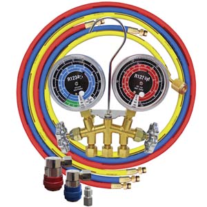

 Checking your starting system on your vehicle One of the most common problems on vehicles is that they simply will not start. There are several different factors that can affect whether or not your vehicle will start. In this article we will discuss some simple tests that will allow you to test your entire starting system. This will help you save money and do it yourself. Ok, the only real tool that you are going to need to test your starting system is a simple multimeter. You can use a simple multimeter such as this